Use the below links to navigate to these sections of this page:
CLTE Coefficient of Linear Thermal Expansion | COF Coefficient of Friction | Compressive Strength | CUT (Continuous Use Temp.) | Dielectric Constant | Dielectric Strength | Dissipation Factor | Elongation | Flammability | Flexural Strength | Hardness | HDT (Heat Deflection Temp.) | Impact | Izod Impact | Melting Point | Modulus | PV & Limiting PV | Specific Gravity | Surface Resistivity | Tensile Impact | Tensile Strength | Tg Glass Transition | UL 94 Flame Class | Water Absorption | Wear Resistance “K” Factor
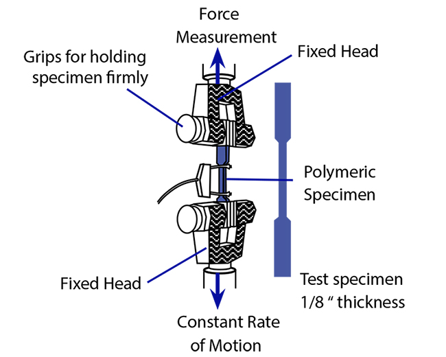
TENSILE STRENGTH (ASTM D 638)
Ultimate tensile strength is the force per unit area required to break a material under tension. It is expressed in pounds per square inch (psi). The force required to pull apart 1 square inch of plastic may range from 1,000 to 50,000 lbs. or higher. Steel and other structural alloys have much higher tensile strengths, such as SS304 at 84 kpsi.
As shown below, for this test, samples are either machined from stock shapes or injection molded. The tensile testing machine pulls the sample from both ends and measures the force necessary to pull the specimen apart (tensile strength), and how much the material stretches before breaking (elongation).
 /
/
Back to Top
ELONGATION (ASTM D 638)
Elongation (which is always associated with tensile strength) is the increase in length at fracture, expressed as a percentage of original length. For example, a strip of writing paper can be pulled apart with almost no visual stretching or elongation. On the other hand, a rubber band may be stretched several times its original length before breaking.
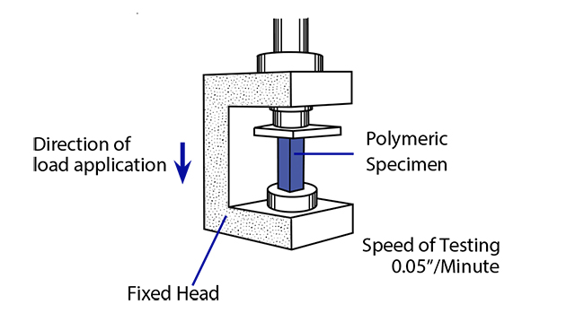
COMPRESSIVE STRENGTH (ASTM D 695)
Compressive strength measures a material’s ability to support a compressive force. See the test schematic below. Always reported as pounds per square inch (psi), this property may indicate one of the following:
Ultimate compressive strength (the maximum stress to rupture a test sample)
Compressive strength at a specific deformation (i.e. 0.1%, 1%,10% – typically used for materials like plastics that may not rupture) Compressive yield strength (the stress in psi as measured at the point of permanent yield, zero slope, and on stress-strain curve)
As shown below, a testing a specimen of 1/2” x 1/2” x 1” is mounted in a compression tool between testing machine heads. An indicator registers the load in psi.
Back to Top
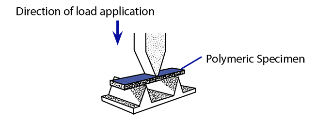
FLEXURAL STRENGTH (ASTM D 790)
Flexural properties measure a material’s resistance to bending under load. The load at yield is the flexural strength of the material and is typically expressed in psi. For plastics, the data is usually calculated at 5% deformation/strain (the loading necessary to stretch the outer surface 5%).
As shown below, a polymeric specimen of 1/8” x 1/2” x 5” is placed on two supports.
Back to Top
MODULUS (TENSILE, COMPRESSIVE, FLEXURAL)
The modulus of elasticity (tensile, compressive or flexural) relates an applied stress to a resultant strain. Since all plastics do not exhibit perfect elasticity upon loading (a defined constant slope as part of their stress/strain curve), a tangent modulus is generally reported. Special consideration must be given when designing for continuous or long-term applied stresses due to plastics' time dependent (viscoelastic) behavior under stress. When time dependent strains must be determined, apparent modulus (creep) values must be used. These data are both time and temperature dependent and generally developed using a DMA (Dynamic Modulus Analyzer). Please contact us for DMA curves for Quadrant materials.
HARDNESS
Hardness is usually reported by one of two test methods – Rockwell (ASTM D 785) or Indentation Hardness / Durometer (ASTM D 2240). The Rockwell test is typically chosen for hard materials such as acetal, nylon, and PEEK where creep is less of a factor in the test results. A test schematic is shown below.
The Durometer is reported for softer materials such as urethane. The two scales do not correlate and cannot be compared. Data from a single scale is best used to compare hardness for one material versus another. Hardness data is best used to compare materials. By itself the test is not an indication of strength, wear performance or abrasion resistance.
Back to Top
IMPACT / TOUGHNESS
A material’s ability to absorb rapidly applied energy is its impact resistance. Impact resistance will vary based upon the shape, size, thickness, and type of material. Various methods of impact testing are very helpful when comparing the relative impact resistance of different materials. The impact tests most frequently used are Izod and Tensile impact. Charpy and Gardner impact tests can also be used to get a complete characterization of a material’s toughness.
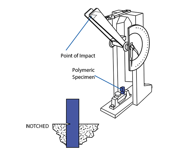
Izod Impact (ASTM D 256)
In this test, a pendulum arm swings to impact a notched, cantilevered beam as shown below. After fracturing the test specimen, the pendulum continues to travel in the same direction, but with less energy. This loss of energy, measured in foot-pounds per inch (ft-lb/in., or J/m) of beam thickness, is known as the Izod impact strength. This test can also be done with either an unnotched specimen or with the notch reversed, in which case it is reported as “unnotched” or “reversed notch Izod” impact strength, respectively.
Back to Top
Tensile Impact (ASTM D 1822)
This test uses a swinging pendulum similar to that used in the Izod impact test, except the sample specimen is a tensile bar. It is mounted, as shown below, to measure the energy required to fracture it (pull it apart) due to rapid tensile loading.

Back to Top
HEAT DEFLECTION TEMPERATURE (ASTM D 648)
The heat deflection temperature is the temperature at which a 1/2” thick test bar, loaded to a specified bending stress, deflects by 0.010 in. (See Below). It is sometimes called the “heat distortion temperature” (HDT). This value is used as a relative measure of the ability of various materials to perform at elevated temperatures short term, while supporting loads.

Back to Top
CONTINUOUS USE TEMPERATURE
This value is most commonly defined as the maximum ambient service temperature (in air) that a material can withstand and retain at least 50% of its initial physical properties after long term service (approximately 10 years). Most thermoplastics can withstand short-term exposure to higher temperatures without significant deterioration. When selecting materials for high temperature service, both HDT and continuous service temperature need to be considered.
Tg GLASS TRANSITION (ASTM D 3418)
The glass transition temperature (Tg) is the temperature above which an amorphous polymer becomes soft and rubbery. It is important to ensure that an amorphous polymer is used below its Tg if reasonable mechanical performance is expected, except when thermoforming.
Back to Top
MELTING POINT (ASTM D 3418)
The temperature at which a semi-crystalline thermoplastic changes from a solid to a liquid.
COEFFICIENT OF LINEAR THERMAL EXPANSION (E 831 TMA)
The coefficient of linear thermal expansion (CLTE) is the ratio of the change in a linear dimension to the original dimensions of the material for a unit change of temperature. It is usually measured in units of in./in./°F. CLTE is a very important consideration if dissimilar materials are to be assembled in applications involving large temperature changes. A thermoplastic’s CLTE can be decreased (making it more dimensionally stable) by reinforcing it with glass fibers or other additives. The CLTE of plastics vary widely. The most stable plastics approach the CLTE of aluminum but exceed that of steel by up to ten times.
Back to Top
FLAMMABILITY
In electrical applications (or any applications where plastic constitutes a significant percentage of an enclosed space), the consequences of exposure to cabin). Flammability tests measure combustibility, smoke generation, and ignition temperatures of materials.
UL 94 FLAMMABILITY CLASS (HB, V -2, V -1, V -0, 5V)
In this test, specimens are subjected to a specified flame exposure. The relative ability to continue burning after the flame is removed is the basis for classification. In general, the more favorable ratings are given to materials that extinguish themselves rapidly and do not drip flaming particles. Each rating is based on a specific material thickness (i.e. UL94 - HB, V-2, V-1, V-0, 5V (See Below).

Back to Top
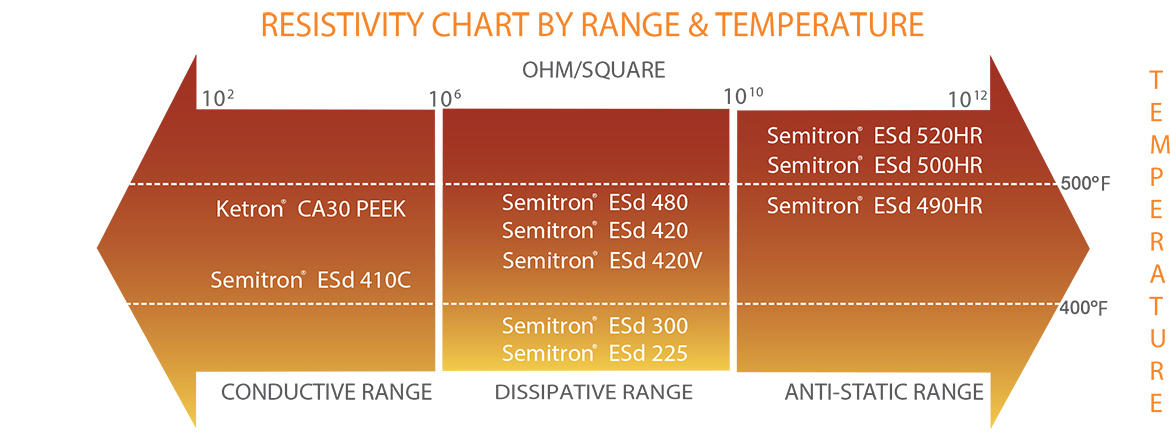
SURFACE RESISTIVITY (EOS/ESD S 11.11)
This test measures the ability of electric current to flow over the surface of a material and is expressed in ohms/square area. The more readily the current flows, the lower the surface resistivity as resistivity continuum. The test electrodes are both placed on the same side of the test specimen. To measure current flow, one must consider that the surface resistivity may be affected by environmental changes such as moisture absorption. Surface resistivity is used to evaluate and select materials for testing when static charge dissipation or other surface characteristics are critical.
• Insulators exhibit resistivities of 10^12 and higher ohm/square
• Antistatic/partially conductive products exhibit resistivities of 10^6 to 10^12 ohm/square
• Conductive products exhibit resistivities of < 10^6 ohm/square
Back to Top
DIELECTRIC STRENGTH (ASTM D 149)
When an insulator is subjected to increasingly high voltages, it eventually breaks down and allows a current to pass. The voltage reached before break down divided by the sample thickness is the dielectric strength of the material, measured in volts/mil. It is generally measured by putting electrodes on either side of a test specimen and increasing the voltage at a controlled rate. Factors that affect dielectric strength in applications include: temperature, sample thickness, conditioning of the sample, rate of increase in voltage, and duration of test. Contamination or internal voids in the sample also affect dielectric strength.
DIELECTRIC CONSTANT (ASTM D 150)
The Dielectric Constant, or permitivity, is a measure of the ability of a material to store electrical energy. Polar molecules and induced dipoles in a plastic will align themselves with an applied electric field. It takes energy to make this alignment occur. Some of the energy is converted to heat in the process. This loss of electrical energy in the form of heat is called dielectric loss, and is related to the dissipation factor. The rest of the electrical energy required to align the electric dipoles is stored in the material. It can be released at a later time to do work. The higher the dielectric constant, the more electrical energy can be stored. A low dielectric constant is desirable in an insulator, whereas someone wanting to build a capacitor will look for materials with high dielectric constants. Dielectric constants are dependent on factors such as frequency, temperature, moisture, chemical contamination and other factors. The values stated in Quadrant’s data is measured at 106 Hertz in carefully conditioned samples.
Back to Top
DISSIPATION FACTOR (ASTM D 150)
The dissipation factor, or dielectric loss tangent, indicates the ease with which molecular ordering occurs under an applied voltage. It is most commonly used in conjunction with dielectric constant to predict power loss in an insulator.
SPECIFIC GRAVITY (ASTM D 792)
Specific gravity is the ratio of the mass of a given volume of material compared to the mass of the same volume of water, measured at 73°F (23°C). (Density of a material divided by the density of water.) Since it is a dimensionless quantity, it is commonly used to compare materials. Specific gravity is used extensively to determine part cost and weight.
Back to Top
WATER ABSORPTION (ASTM D 570)
Water absorption is the percentage increase in weight of a material due to absorption of water. Standard test specimens are first dried then weighed before and after immersion in 73°F (23°C) water. Weight gain is recorded after 24 hours, and again when saturation is reached. Both percentages are important since they reflect absorption rate. Mechanical and electrical properties and dimensional stability are affected by moisture absorption.
COEFFICIENT OF FRICTION (ASTM D 3702 / QTM 55007)
Coefficient of friction (COF) is the measure of resistance to the sliding of one surface over another. Testing can be conducted in a variety of ways although thrust washer testing is most common. The results do not have a unit of measure associated with them since the COF is the ratio of sliding force
to normal force acting on two mating surfaces. COF values are useful to compare the relative “slickness” of various materials, usually run unlubricated over or against polished steel. Since the value reflects sliding resistance, the lower the value, the “slicker” the bearing material.
Two values are usually given for COF:
• “Static” COF refers to the resistance at initial movement from a bearing “at rest”.
• “Dynamic” COF refers to the resistance once the bearing or mating surface is in motion at a given speed.
Back to Top
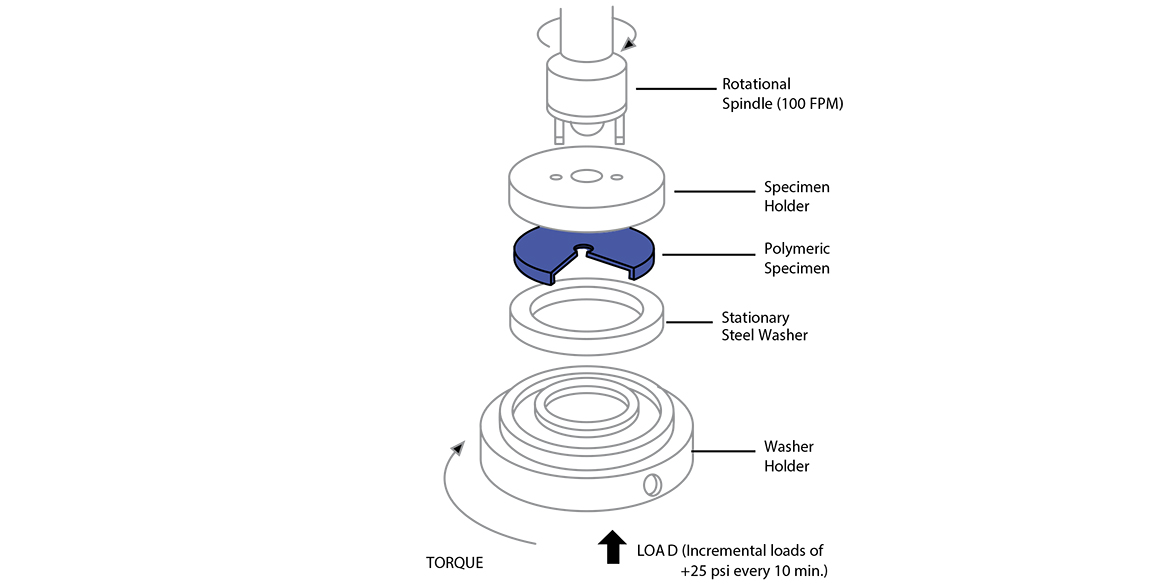
PV AND LIMITING PV (QTM 55007)
Two factors that must be considered when reviewing a bearing application:
• P = the load the bearing will be subjected to (measured as pressure (lbs./in2))
• V = the speed of the contact surfaces (velocity (ft./min.))
The result of multiplying P by V is referred to as the PV for a bearing application. The combination of pressure and velocity causes the generation of frictional heat at the bearing surface. This heat can contribute to premature bearing failure due to overheating if an application PV exceeds the capability of a plastic bearing material. Limiting PV is the maximum PV to which a bearing material should be subjected in unlubricated conditions. A material subjected to a PV in excess of its Limiting PV may fail prematurely due to surface melting or excessive wear.
To test for Limiting PV, a thrust washer set-up is utilized (See Below). The plastic sample is rotated at 100 feet per minute (FPM) and is exposed to incremental loads of 25 psi every 10 minutes while bearing temperature is measured. The test has ended when the system temperature exceeds 300°F, or excessive deformation, or rapid wear of the plastic is detected. The resulting PxV combination is determined and divided by a safety factor of 4.
Enhanced bearing and wear materials, such as Nylatron® NSM Type 6 Nylon, combine a low wear rate (12) with high Limiting PV capabilities (15,000 psi-FPM dry) – allowing much wider design flexibility and greater safety factors.
Back to Top
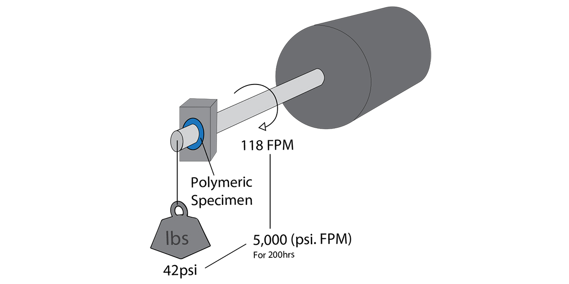
WEAR RESISTANCE / “K” FACTOR (QTM 55010)
The wear factor (“k” factor) relates bearing surface wear rate to the variables of pressure, velocity and time.
This test uses a “journal bearing” set-up (See Below) with an actual bearing exposed to a constant load and speed (118 FPM, 42 psi = 5,000 PV). After 200 hours (T=hours) of continuous running, the radial wear of the bearing is measured and (k) is calculated.
The lower the “k” factor, the greater the wear resistance. Results from this test can vary significantly if different pressure and velocity conditions are used. Consistency of test methods is critical if “k” factors are used to compare various materials.
Back to Top